Laying of underground GI pipes for water supply–Plumbing Systems
Galvanized Iron Pipes Technical Specifications
The pipes shall be galvanized mild steel welded pipes and screwed and socketed tubes conforming to the requirements of IS: 1239-1982, for medium grade. They shall be of the diameter (nominal bore {NB}) specified in your drawing.
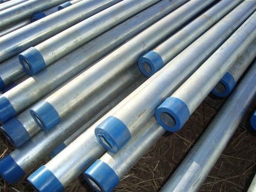
The sockets shall be designated for the respective nominal bores of the pipes for which they are intended. The pipes and sockets shall be cleanly finished well galvanized in and out and free from cracks surface flaws, laminations, and other defects.
All screwed threads shall be clean and well cut.
Construction of bituminous road-Process in Bituminous Road Construction
All GI tubes and sockets shall have pipe threads which confirm to the requirements of IS: 554 screwed tubes shall have taper threads while the sockets shall have parallel threads.
The fittings shall be of malleable cast iron or mild steel tubes complying with IS: 1879 (Part I to X) with all the appropriate requirements as specified for pipes.
The galvanized mild steel pipes and galvanized mild steel fittings shall be inspected at site before use to verify that they conform to the specification. The defective pipes shall be rejected.
Where the pipes have to be cut or re-threaded, the ends shall be carefully filed out so that no obstruction to bore is offered. The end of the pipes shall then be threaded conforming to the requirements of IS: 554 with pipe dies and taps carefully in such a manner as will not result in slackness of joints when the two pipes are screwed together.
The taps and dies shall be used only for straightening screw threads which have become bent or damaged and shall not be used for turning of the threads so as to make them slack, as the latter procedure may not result in a water tight joint. The screw threads of pipes and fitting shall be protected from damage until they are fitted.
Process of Laying of GI pipes for water supply
The pipes shall be cleaned of all foreign matter before being laid in jointing the pipes, the inside of the socket and the screwed end of the pipes shall be oiled and rubbed over with white lead and a few turns of spun yarn wrapped round the screwed end of the pipes.
The end of the galvanized iron pipes shall then be screwed in the socket, tee etc. with the pipe wrench. Care be taken that all galvanized iron pipes and fittings are properly jointed so as to make the joints completely water tight and pipes are kept at all times free from dust and dirt during fixing.
Burr from the joint shall be removed after screwing. After laying, the open ends of the galvanized iron pipes is temporarily plugged to prevent flow of water, soil or any other foreign matter. Any threads exposed after jointing is to be painted and in the case of underground piping coated with approved anti-corrosive paint to prevent corrosion.
If the galvanized iron pipes and fittings are laid in trenches, the widths and depths of the trenches for different diameters of the pipes shall be as in the table given below:-
| Diameter of pipe | Width of trench | Depth of trench |
| 15 mm to 50mm | 30 cm | 60 cm |
| 65 mm to 100mm | 45 cm | 75 cm |
The work of excavation and refilling shall be done true to line and gradient in accordance with general specifications for each work in trenches.
After successful pressure testing, the pipe line to be painted a coat of APCOMIN ROZC primer PQ 1741, 25 micron DFT followed by two coats of Bituminous paint of approved make OR pipes shall be wrapped with thermo-fusible composite film 4 mm thick made out of fiber glass mat base with polymeric coatings (like PYKOTE) of approved make, as per the procedure recommended by the manufacturer.
The pipes shall be laid on a layer of 7.5 cm sand and filled up to 15 cm above the pipes. The surplus earth shall be disposed off as directed.
When excavation is done in rock the bottom shall be cut deep enough to permit the pipes to be laid on a cushion of sand 7.5 cm minimum. In case of big diameter pipes where the pressure is very high blocks of cement concrete 1:2:4 (1 cement: 2 coarse sand : 4 graded stone aggregate of 20 mm nominal size) shall be constructed on all bends to transmit the hydraulic thrust.
Gi Pipes Water Distribution Pipes Testing Methods-
After laying and jointing, the pipes and fittings shall be inspected under working conditions of pressure and flow.
The pipes and fittings after they are laid shall be tested to hydraulic pressure of 10 kg/sq.cm. The pipes shall be slowly charged with water allowing all air to escape and avoiding all shock. The draw off takes and stop cocks shall then be closed and specified hydraulic pressure shall be applied gradually.
Pressure gauge must be accurate and preferably should have been recalibrated before the test. The test pump having been stopped the test pressure should maintain without loss for at least half an hour. The pipes and fittings shall be tested in sections as the work of laying proceeds, keeping the joints exposed for inspection during the testing.
Mode of Measurement GI pipes for water supply--Plumbing Systems
GI pipes with fittings completely fixed in position shall be measured and paid for the finished center line lengths and the measurement shall be in Running Meter
Leave a Reply